Originally published in 2016, and substantially rewritten in 2026 to reflect a decade of new hardware and software!
If you’re keeping plants or animals in a terrarium or vivarium, an electronic controller can provide a more stable environment than you can ever hope to achieve using regular timers. By integrating your terrarium into the Internet-of-Things using a Raspberry Pi, it’s possible to create a highly-extensible system which offers automation, data visualisation, alerts, and pretty much anything you or your plants (or even pets!) could want.
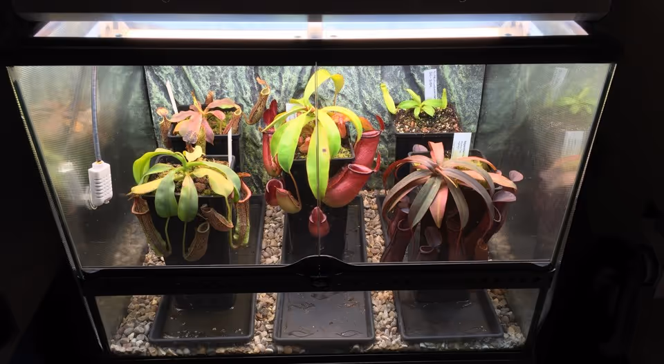
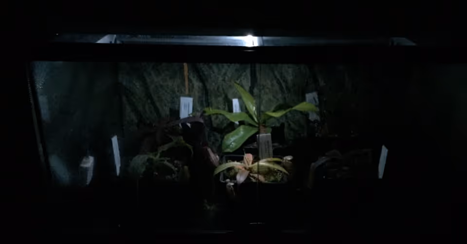
Here’s an example of the live conditions inside my own terrarium:

In this guide, I’ll be giving step-by-step instructions for building a simple Terrarium Controller using a Raspberry Pi Zero 2 W, an off-the-shelf smart plug, and a single sensor - for a total cost of around £60 (or $90 USD). You don’t have to be an electrician or a programmer; the only skills required are basic wiring and a bit of comfort with the Raspberry Pi command line. Let’s get started.
Parts Required
- Raspberry Pi Zero 2, SD card, case, and USB power supply. Amazon - approx. £30 / $45. A Raspberry Pi 4 or 5 will also work but is overkill unless you want other more complex functionality.
- AM2302 temperature & humidity sensor. Amazon - approx. £10 / $15
- A WiFi smart plug with a local API. I recommend the Shelly Plus Plug S, which exposes a local HTTP API out of the box (no cloud account required). Amazon / Shelly - approx. £22 each. Buy one per device you want to switch on or off based on sensor readings.
- Male-female jumper wires (you only need three).
- Solid core prototyping wire, 22AWG / 0.6mm - for extending the sensor leads into your terrarium.
- Heat shrink tubing, 1m, approx 5mm wide.
- Small suction cup to mount the sensor inside the tank.
- Adhesive-backed Velcro for mounting the Pi case.
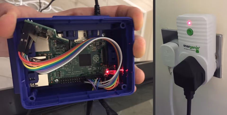
Side note: This guide previously recommended the Energenie Pi-mote - a 433MHz transmitter board that plugs onto the Pi’s GPIO and controls dedicated remote sockets. It still works (gpiozero ships with first-class support), but smart plugs are now cheaper per outlet, easier to set up, and don’t hog the GPIO. I’ve preserved the original Energenie instructions further down the page for anyone who already owns the kit or prefers a fully-offline RF approach.
Prerequisites
- Some kind of terrarium, vivarium, or pet enclosure.
- A Raspberry Pi Zero 2 W (or 4/5) running an up-to-date version of Raspberry Pi OS. Use the Raspberry Pi Imager - it lets you preconfigure WiFi, SSH, and your username before the SD card ever leaves your laptop. If you’re new to the Pi, the official documentation covers everything you need to get to this point.
- For tools, you’ll need a screwdriver, wire strippers, and either insulation tape or - preferably - a soldering iron and heat-shrink tubing.
Variables
The four main variables in any terrarium are temperature, humidity, light, and water. These are the things which you need to monitor and control if your plants or pets are going to be happy. For the purposes of our Terrarium Controller, we’ll assume you have watering under control; it’s an easy task and infrequently required in terrariums which are sealed or nearly-sealed. Instead, we’ll be focusing on the first three.
Light is probably easiest to control. Most terrarium owners set fluorescent or LED lights along the top of their tank and switch these on and off at regular intervals. Lighting will be simple to automate, since we needn’t respond to anything other than the time.
Temperature is more difficult. Most lighting fixtures provide a certain amount of heat, and this usually needs to be dissipated or supplemented depending the type of plants or animals you’re keeping. If your home is already quite warm, fans may be necessary to blow away excess heat from the fixtures. If your home tends towards the chilly side, you’ll probably need a heating mat under your terrarium. Under some circumstances, it might be necessary to alternate between both.
Finally, there’s humidity: in a sealed environment it’s generally quite easy to keep humidity above 80%. While owners of larger terrariums might consider humidifiers or foggers, occasional watering and misting should provide your terrarium with all the moisture it needs. If, on the other hand, you need to lower the humidity, you’ll probably need a small interior fan to circulate the steamy air and increase ventilation.
Whichever route you go down, the key point is this: we need to switch numerous mains-powered components on or off depending on (a) the time, and (b) the current conditions inside the terrarium.
Hardware
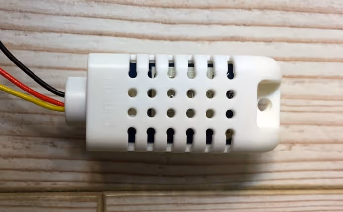
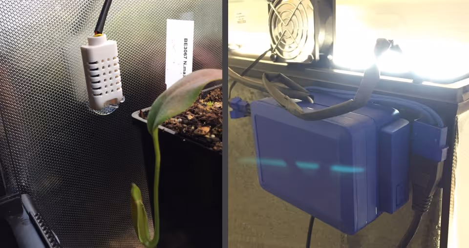
The first component we’ll wire into the Pi’s GPIO is a combined temperature and humidity sensor. The AM2302 is a wired version of the common DHT22 sensor in a convenient plastic housing. It’s easy to use, fairly cheap (about £10), and a decade after I first wrote about it, still the obvious choice for this kind of project.
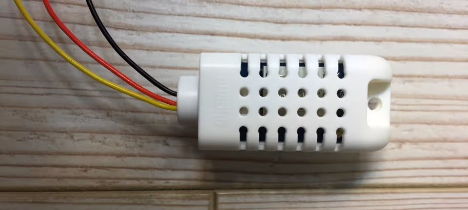
The AM2302 needs three connections: power, ground, and data. The official spec lists 3 to 5V power with a built-in 5.1KΩ resistor, and the documentation recommends the higher voltage for wire lengths over 1 metre. For a Pi mounted on the back of the tank, you’re unlikely to exceed that, so wire it as follows: red to physical pin 1 (3v3 power), black to pin 9 (ground), and yellow to pin 7 (GPIO 4 / data). The pinout.xyz reference is invaluable if you’re unsure which pin is which.
So, how do we switch other components - fans, heaters, lights - on or off based on our sensor readings? Running anything off the Pi’s own power output is risky beyond the smallest of fans, and using relays to control mains electricity directly is dangerous unless you really know what you’re doing. The safe, easy answer in 2026 is a WiFi smart plug.
The Shelly Plus Plug S is ideal for this project: it has a local HTTP API built in, doesn’t require a cloud account, and sits anywhere in your house on your local network. Plug your fan (or heater, humidifier, etc.) into it, follow Shelly’s first-time setup to put it on your WiFi, and note its local IP address from your router’s admin page or the Shelly app. That’s it - no GPIO wiring, no separate radio transmitter, and you can add as many plugs as you have devices to control.
If WiFi smart plugs aren’t your thing, see the Energenie alternative at the end of this guide.
Software
Make sure your Pi is up-to-date and install the dependencies we’ll need:
sudo apt update
sudo apt full-upgrade -y
sudo apt install -y python3-pip python3-venv libgpiod2
Modern Raspberry Pi OS (Bookworm and later) prevents pip from installing packages into the system Python - a good thing, but it means we need a virtual environment for our project. Create one in a fresh terrarium folder:
mkdir -p ~/terrarium && cd ~/terrarium
python3 -m venv .venv
source .venv/bin/activate
Inside the venv, install the two libraries we need:
- Adafruit’s CircuitPython DHT library to talk to the AM2302
- Requests to send HTTP calls to the smart plug and ThingSpeak
pip install adafruit-circuitpython-dht requestsNote: This guide previously used the older Adafruit_Python_DHT library, which Adafruit have since archived and deprecated in favour of the CircuitPython version above. The API is slightly different but the principle is the same.
With the sensor connected to the GPIO as described in the previous section, you can do a quick read with a one-liner from inside the venv:
python3 -c "import adafruit_dht, board; d=adafruit_dht.DHT22(board.D4); print(f'{d.temperature:.1f}°C, {d.humidity:.1f}%')"If everything is wired correctly, you’ll see something like:
26.1°C, 52.1%It’s worth noting that this command can sometimes return a RuntimeError even if you have wired everything correctly. As Adafruit explain, this is a limitation of using DHT sensors on Linux: the OS doesn’t guarantee the program enough scheduler priority to reliably catch the sensor’s precise signal timing. Just try again - in our actual script we’ll retry automatically.
Next, set up your Shelly Plus Plug S. Plug it in, run through the first-time WiFi setup using the Shelly app, and grab its local IP from the app or your router. Test that you can switch it on and off with a simple HTTP call from your Pi:
curl "http://<plug-ip>/rpc/Switch.Set?id=0&on=true"
curl "http://<plug-ip>/rpc/Switch.Set?id=0&on=false"
If you hear the relay click and the LED on the plug change colour, you’re good. The full local API is documented on Shelly’s developer site.
Finally, sign up for a free ThingSpeak account. ThingSpeak is an open data platform now owned by MathWorks; the free tier is generous enough for a hobby project like this. Create a channel with two fields: field1 for temperature, field2 for humidity. Grab your channel’s Write API Key - you’ll paste it into the script in a moment.
Now we’re ready to write the program for the Terrarium Controller.
Scheduling & Data Viz
We’re going to write three tiny scripts which the Terrarium Controller will execute on a schedule.
The first two control our lighting - lights-on.py and lights-off.py - and run once a day at sunrise and sunset (or whenever suits your plants). With the smart plug approach each is just one HTTP call. As I said earlier, automating routine on/off cycles like this is optional; in most situations a regular mechanical timer does the job just fine.
The third script - monitor.py - runs once every two minutes. It needs to:
- Check the conditions inside the terrarium
- Activate or deactivate the smart plug as required
- Log the sensor readings to ThingSpeak
One caveat, before we continue: in this section I’ve used my own terrarium as an example. I live in southern England where it’s pretty cold most of the year, growing plants which need warm days, cool nights, and constant high humidity. As such, the only component dependent on my sensor reading - at least for this starter script - is a set of cooling fans for my lighting fixture. The principles are broadly relevant to setups of all kinds, but you’ll need to adjust thresholds and components for your local climate and the plants you’re growing.
The code is below.
#!/usr/bin/env python3

# monitor.py - reads an AM2302 sensor, controls a Shelly
# Plus Plug S, and logs data to ThingSpeak. MIT license.
# https://tomscarnivores.com/tech/raspberry-pi-terrarium-controller/

import time
import board
import adafruit_dht
import requests

SHELLY_IP = "192.168.1.50"
THINGSPEAK_KEY = "XXXXXXXXXXXXXXXX"
TEMP_THRESHOLD = 28  # °C - activate cooling fans above this

sensor = adafruit_dht.DHT22(board.D4)


def read_sensor(retries=5):
    for _ in range(retries):
        try:
            return sensor.temperature, sensor.humidity
        except RuntimeError:
            time.sleep(2)
    return None, None


temperature, humidity = read_sensor()

if temperature is None or humidity is None:
    requests.post(
        "https://api.thingspeak.com/update.json",
        data={"api_key": THINGSPEAK_KEY, "status": "failed to get reading"},
    )
else:
    state = "true" if temperature > TEMP_THRESHOLD else "false"
    requests.get(
        f"http://{SHELLY_IP}/rpc/Switch.Set?id=0&on={state}",
        timeout=5,
    )
    requests.post(
        "https://api.thingspeak.com/update.json",
        data={
            "api_key": THINGSPEAK_KEY,
            "field1": temperature,
            "field2": humidity,
        },
    )
We’re recording both temperature and humidity, and switching the smart plug on whenever the temperature exceeds 28°C. By tweaking the threshold, adding extra plugs, or inverting the logic, it’s easy to extend this same pattern to heating mats, humidifiers, circulation fans, and anything else in your terrarium.
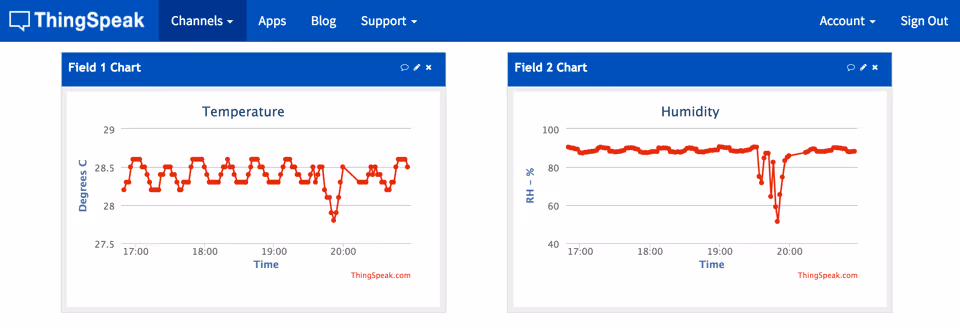
Run the script a few times from your venv (python3 monitor.py) and confirm two things: the smart plug switches state when you cross the threshold, and your data is showing up on the ThingSpeak channel chart. Try lowering the threshold below your room temperature to force the plug on, then raise it again.
Going further: Home Assistant. If you’d rather have a polished web dashboard, on-device alerts, voice control, and the ability to integrate dozens more sensors and devices without writing scripts at all, take a look at Home Assistant. It runs on the same Pi (a Pi 4 or 5 is recommended for HA itself), supports the AM2302 and Shelly natively, and can replace monitor.py entirely with a few lines of YAML automation. It’s overkill for a single tank, but invaluable if you keep growing the setup.
Once you’re happy, set the three scripts to run on a schedule with cron. There’s nothing extra to install. If you’ve never used cron before, this Pi Hut tutorial is a friendly intro.
Open the crontab with crontab -e and add the three lines below. Because we’re running inside a venv, we point cron at the venv’s Python interpreter rather than the system one. The template below provides a 14-hour photoperiod (lights on at 7:01, off at 21:01), with the monitor running every 2 minutes. The 1-minute offset just keeps the monitor and lighting jobs from ever firing in the same second.
*/2 * * * * /home/pi/terrarium/.venv/bin/python3 /home/pi/terrarium/monitor.py
1 7    * * * /home/pi/terrarium/.venv/bin/python3 /home/pi/terrarium/lights-on.py
1 21   * * * /home/pi/terrarium/.venv/bin/python3 /home/pi/terrarium/lights-off.py
(Replace /home/pi/ with your actual home directory if you set a custom username during Imager setup.)
Wiring & Installation
It’s time to install your Terrarium Controller.
You could do a quick and dirty job with insulation tape, but the resulting mess would just distract from the plants or animals in your terrarium - and high humidity tends to peel tape off within weeks. I’d suggest firing up the soldering iron and using heat-shrink tubing instead; it doesn’t take much effort to create something tidy and unobtrusive.
First, decide where the Pi is going to live. Assuming the sensor wire enters through the top of your terrarium, it should be possible to mount the Pi on the back of the tank and route the cable through a port or other narrow gap. The AM2302 has a small hole which is perfect for holding a small suction cup, letting you mount it wherever the airflow best represents the conditions you care about.
Measure the lengths of wire you need, solder the sensor leads to your jumper extensions, and use heat-shrink tubing to bundle the three wires neatly. I find 5mm tubing ideal - shrinking it would technically need a heat gun, but it’s not strictly necessary for this kind of build.
Mount the Pi case on the back of the tank using adhesive-backed Velcro, route the sensor into the growing area, plug your smart plug into a nearby socket with the fan (or heater) plugged into that, connect the Pi’s USB power adapter, and you should be good to go!
Future Extensibility
One of the best things about this project is its potential for extensibility. The initial build offers a great level of automation, but you can add as many smart plugs as you have devices to control, and the Pi still has a full GPIO header free for additional sensors.
A few directions worth exploring:
- Build a small alphanumeric or e-paper display to show current conditions on the front of the tank
- Add a soil moisture sensor to monitor your plants’ substrate
- Hook up a Pi camera module so you can check on pets when you’re not around
- Wire a spare GPIO pin to an ultra-bright LED in the lid for a programmable moonlight effect, as in the photo above
- Move the whole thing to Home Assistant for a graphical UI, alerts, and integration with the rest of your smart home
- For sensor-only nodes (no Pi-side logic at all), an ESP32 with ESPHome is even cheaper and lower-power than a Pi - talk to it over MQTT or via the Home Assistant integration
Just remember to calculate the power requirements of any GPIO accessories you install.
Alternative: Energenie Pi-mote
If you’d rather keep everything on a fully-offline radio link - or you already own an Energenie Pi-mote starter kit - the original 2016 method still works, and gpiozero still ships with first-class support. The downsides are that the Pi-mote board sits on top of the GPIO and needs careful cabling to coexist with the AM2302, and the radio sockets need a couple of metres of physical separation from each other.
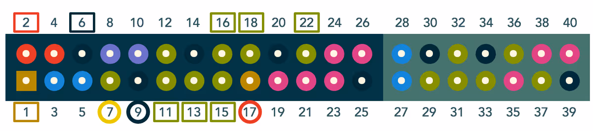
Despite hogging the entire GPIO, the Pi-mote transmitter only needs nine pins to function: physical pins 1, 2, and 6 (power and ground), plus 11, 13, 15, 16, 18, and 22 (data). I’ve prepared an easily-readable diagram below.
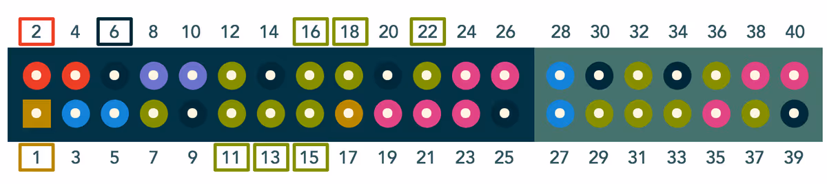
To install the AM2302 sensor alongside the Pi-mote, use a short ribbon of male-female jumper wires so both can share the GPIO header. Wire the sensor’s yellow to pin 7 (data), black to 9 (ground), and red to 17 (3v3 power). These are marked with circles below.
Setting up an Energenie socket involves putting it into learning mode and assigning it to a group. When a socket is in learning mode, the LED on the front flashes slowly. If your new socket doesn’t enter learning mode automatically when plugged in, hold the green button on the front for 5 seconds and release when the LED starts flashing. The socket will then react to the first signal it receives.
To assign it to group 2, for example, run this Python in your venv (after pip install gpiozero):
from gpiozero import Energenie
newsocket = Energenie(2, initial_value=True)
Program sockets one at a time, otherwise they’ll all react to the same signal. Once paired, swap the requests.get(...) line in monitor.py for Energenie(1, initial_value=True/False) to switch components on and off.
Energenie now also offer a multi-outlet mains lead with individually-controllable sockets, removing the old separation requirement; the quick-start guide walks through that variant.
Hope this has been useful. Thanks for reading!